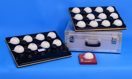
FST - Hemispheres

27.000 - FST Hemispheres:
Application:
The hemisphere method describes near-bottom flow
conditions in watercourse. The method is based on a simple
concept:
The weight of a hemisphere exposed to a flow is moved by a given
current from a reform plate. The set of hemispheres consists of 21
identical hemispheres with different specific gravity.
The modern description of the quality of running waters requires
a solid understanding of physical conditions.
Modern conservation of running water and restoration of nature
aims at natural variation of the physical environment of running
water, considering channel form, as well as discharge and bottom
space sediment.
This complicates the use of traditional methods of measuring flow
for example propeller instruments, well-known to be unreliable for
measuring current in weeded running water or near the bottom of the
stream.
The hemispere method is an attractive alternative/supplement for a
detailed evaluation of the physical environment when restoring
running water, establishing spawnbanks, etc.
The method is especially suitable if the flow forces prevailing at
the stream - bottom are of interest.
Field procedures for FST Hemispheres:
From Statzner, B and R. Müller. 1989. Standard hemispheres as indicators of flow characteristics in lotic benthos research. Freshwater Biology 21: 445-459.
- Place the Plexiglas plane in a shallow (ideally 1,8 cm deep) horizontal pit dug in the stream bottom (Fig. 1).
- Make sure the plane is level (a slope of less than 2,5% in each direction). Place small stones under the corners in coarse substrate to make the plane horizontal
- Place the hemispheres on the plane, one after another, noting the densest hemisphere that moved.
- The placement procedure for each hemisphere is as follows:
- Hold the hemisphere with one hand slightly above the plane with the brass wire loop facing downstream and the monofilament line loosely held by the other hand (Fig. 1).
- Bring the upstream edge of the hemisphere into contact with the plane.
- Allow the hemisphere to drop down between the fingers completely to the plane - do not press the hemisphere down onto the plane
- Slowly remove the hand from the area.
- Note the heaviest hemisphere that moves on the plane (short movements of less than 2 cm should be considered artifacts and should be neglected).
- The density of the hemispheres can be found in table 1.
LITERATURE:
Standard hemispheres as indicators of flow characteristics in
lotic bentos research.
Bernhard Statzner & Rainer Müller, Zoologisches Institut der
Universitat Karlsruhe, W.Germany, Freshwater Biology (1989) 21, 445
- 459
Calibration of FST-hemispheres against bottom shear stress in a
laboratory flume.
Freshwater Biology (1991) 26, 227 - 231
Frutiger, A. & Schib, J.-L. (1993) : Limitations of
FST-hemispheres in lotic benthos research. - Freshwater Biology 30,
463 - 474
Statzner, B. (1993) : Response to Frutiger & Schib (1993)
"Limitations of FST-hemispheres in lothic benthos research". -
Freshwater Biology 30, 475 - 483
Dittrich, A. & Schmedtje, U. (1995) : Indicating shear stress
with FST-hemispheres - effects of stream-bottom topography and
water depth. Freshwater Biology 34, 107 - 121
B. Statzner * F. KoPunann ** and A.G. Hildrew. ***
* URA CNRS "Ecologie des Eaux Douces" University of Lyon 1,
France.
** Bayerisches Landesamt für Wasserwirtschaft München
Germany
*** Queen Mary and Westfield College, London U.K.
| Specificatins | |
| Material: | Pressure molded polycarbonate thickness 2,5 mm |
| Calibration: | No. 1 - 21 star metal with screwed and glued bottom plate |
| Tolerance: | Specific gravity better than 1 % |
| Capsuling: | Hermetically welded in plastic |
| Baseplate: | PVC with ballast inlay (lead) and inlayed tube level for correct horizontal positioning |
| Surface: | Sprayer sealed (algae-fusing surface) |
| Transportation: | Alloy transport box with plastic inserts |
| Application: | |
| Current velocity: | 0 - 4 m/sec. |
| Temperature: | - 10 to + 40 Cº (storing: -20 to +50 Cº) |
| Maintenance: | None - or simply wipe off |
|
Sphere # |
Density (g m³) |
|
Sphere # |
Density (g m³) |
|
Sphere # |
Density (g cm³) |
|
1 |
1.015 |
|
8 |
1.439 |
|
15 |
3.361 |
|
2 |
1.031 |
|
9 |
1.624 |
|
16 |
3.795 |
|
3 |
1.063 |
|
10 |
1.834 |
|
17 |
4.284 |
|
4 |
1.095 |
|
11 |
2.070 |
|
18 |
4.836 |
|
5 |
1.129 |
|
12 |
2.337 |
|
19 |
5.460 |
|
6 |
1.199 |
|
13 |
2.637 |
|
20 |
6.166 |
|
7 |
1.274 |
|
14 |
2.987 |
|
21 |
6.958 |